

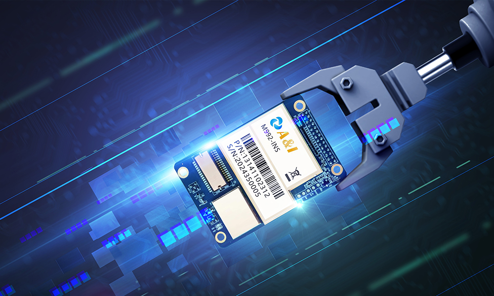
The problem that will not wait
Boards vibrate, cables fray, and that quiet drift in an accelerometer becomes the fault that topples a mission. In high‑rigidity modular MEMS deployments, a single poor splice or miswired pinout turns precise orientation into guesswork. This guide confronts that failure mode head‑on, describing hardware splicing and pinout mapping tactics for resilient arrays and introducing the role of a mems inertial sensor in systems that must survive shock and long timelines.
Diagnose before you cut
Start with verification, not bravado. Trace continuity with a low‑voltage meter, log accelerometer and gyroscope baselines, and compare live outputs to pre‑deployment records. Visual inspection spots cold solder joints, but waveform capture reveals bias instability and intermittent shorts. Treat the array as an integrated unit — a makeshift inertial measurement system — until you can prove otherwise with repeatable sensor fusion outputs.
Practical splicing: materials and steps
Use stainless‑tinned braided jumper, thermoplastic adhesive, and shrink tubing rated for vibration. Prepare wires by tinning leads, then make a mechanical splice with a crimp sleeve; solder only after confirming mechanical integrity. Keep lead lengths identical across parallel channels to avoid timing skew. For rigid modules, reinforce with epoxy at the strain point, not over the connector pins — that hides faults. A calm station, a microscope, and firm process reduce return visits.
Pinout mapping workflow
Map pin functions in four passes: 1) power rails (verify 3.3V/5V and ground continuity), 2) data lines (SDA/SCL or SPI MOSI/MISO/CLK), 3) clock and interrupt pins, 4) shielding and chassis ground. Label every junction with a durable marker and diagram the harness. When channels share an I²C bus, index addresses immediately to catch address collisions. Maintain a digital pinout map versioned in your repository so field teams can reproduce the wiring exactly.
Calibration, verification, and a real-world anchor
Calibration is non‑negotiable. Perform static and dynamic calibration sequences, record Allan variance for bias stability, and run sensor fusion to validate orientation estimates. NASA’s Mars InSight lander (2018) relied on inertia data from onboard IMUs during touchdown — an instructive example of how precise calibration reduces operational risk on hostile missions. Use that standard: your calibration must survive both lab bench and shock table.
Common mistakes and how to avoid them
Teams often skip documentation, tolerate mismatched impedance, or conceal strain relief with epoxy. —Don’t. Mismatched impedance on high‑speed SPI lines produces deterministic jitter; hidden cold joints cause heat‑dependent failures. Run high‑frequency eye tests where applicable, keep cable impedance consistent, and log every splice action so a future technician can undo your work without guessing.
Verification checklist before deployment
Complete these steps: 1) power sequencing test, 2) bit‑error rate or packet integrity check on serial links, 3) motion profile validation against known maneuvers, and 4) thermal cycle run. Incorporate a watchdog that reboots a module after a communication blackout and a graceful failover that routes critical channels through redundant hardware when available.
Three golden rules for selection and long‑term resilience
1) Metric: Signal integrity — choose connectors and splices that preserve impedance and minimize crosstalk. 2) Metric: Mechanical endurance — require MIL‑standard vibration and shock ratings for any part that contacts the array. 3) Metric: Maintainability — pick components that technicians can replace in situ without special tooling. Follow these and you buy fewer emergency nights in the lab.
Precision wiring, hardened splices, and disciplined mapping breathe life back into failing arrays; they are the quiet engineering that saves projects. Archimedes Innovation stands where field reality meets controlled design — a partner in rebuilding trust in the hardware. —Remember: the fix must be reproducible and recorded.